SUMMARY - PRINTED CIRCUIT BOARDS
V. Ryan
© 2005 - 2009
 |
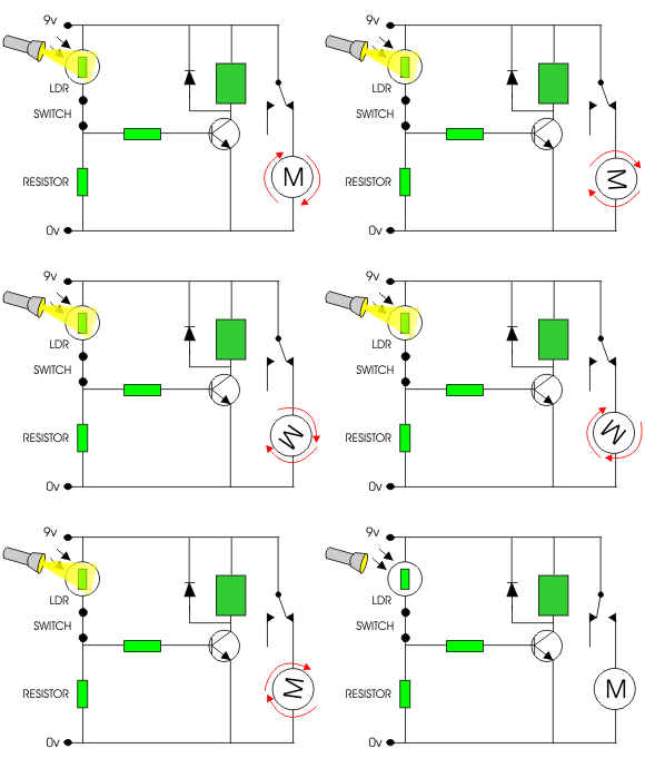
Circuits normally start life as a circuit diagram
drawn on software such as Crocodile Technology. Opposite is an example
of a light sensor circuit drawn in this way. Crocodile Technology can
simulate circuits working.
When the light level is low the resistance of the LDR is high. This prevents current from flowing to the base of the transistor. Consequently the motor does not rotate. However, when light shines onto the LDR its resistance falls and current flows into the base of the transistor and the motor rotates. |
|
|
|
 |
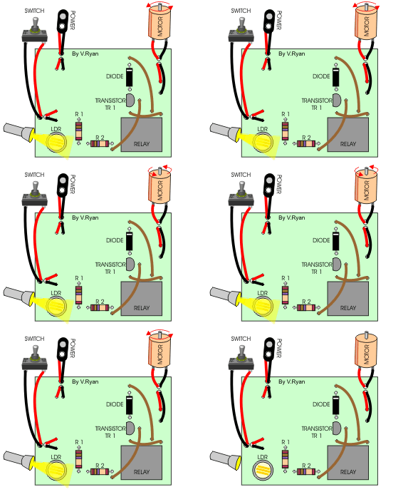
A circuit design can be exported from Crocodile
Technology to Real PCB, which converts it to a PCB layout, ready for
manufacture.
This is a view of a light sensor circuit with its components soldered to the manufactured PCB. The copper tracks are on the underneath side of the PCB. The components are arranged on the top side of the board. Sometimes software such as Real PCB cannot connect all the components with tracks as it would mean that they would cross each other. ‘Fly wires’ (the brown wires) join components that cannot be connected by the copper tracks. |
No comments:
Post a Comment