Monday, February 3, 2014

Robot voice circuit circuit diagram

Robot voice circuit circuit diagram

robot voice circuit schematic
Some flexibility in the playback mode allows individual messages to be linked together; each recorded message is terminated by an EOM (End Of Message) flag when it is stored in the chip. Instead of storing complete phrases like ‘obstacle ahead’ for example it is more efficient to store ‘obstacle’ then ‘ahead’, ‘to the right’, ‘to the left’ and ‘behind’ and likewise for numbers ‘one’, ‘two’, ‘hundred’ ‘point’ etc allows voicing of the complete range of numbers from these basic elements.
The minimum playback circuit shown in uses the A0, PD, /CE and /EOM signals interfaced to the robot microcontroller. For playback PD is reset to ‘0’ and to play the first message a low pulse is given on /CE. With A0 at ‘0’ playback occurs at normal speed but with A0 at ‘1’ the chip enters ‘fast forward’ mode where it advances through the message at 800 times its normal playback speed. When the third message needs to follow the first for example, the processor sets A0 to ‘1’ and pulses /CE low to fast-forward through the second message, waiting for the /EOM flag to go low. Once this occurs A0 is reset to ‘0’ and a low pulse on /CE plays back the third message.
The /EOM output pulse can be less than 10 ms wide so it is better to use it to interrupt the processor rather than just poll its status.
Sunday, January 12, 2014

SUMMARY PRINTED CIRCUIT BOARDS

SUMMARY - PRINTED CIRCUIT BOARDS
V. Ryan © 2005 - 2009

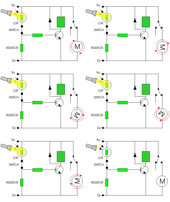
Circuits normally start life as a circuit diagram drawn on software such as Crocodile Technology. Opposite is an example of a light sensor circuit drawn in this way. Crocodile Technology can simulate circuits working.
When the light level is low the resistance of the LDR is high. This prevents current from flowing to the base of the transistor. Consequently the motor does not rotate.
However, when light shines onto the LDR its resistance falls and current flows into the base of the transistor and the motor rotates.
 
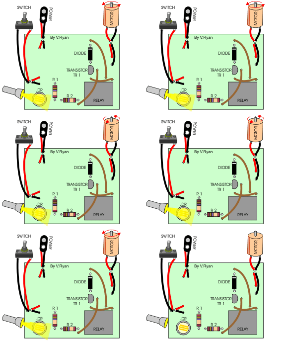
A circuit design can be exported from Crocodile Technology to Real PCB, which converts it to a PCB layout, ready for manufacture.
This is a view of a light sensor circuit with its components soldered to the manufactured PCB. The copper tracks are on the underneath side of the PCB. The components are arranged on the top side of the board.
Sometimes software such as Real PCB cannot connect all the components with tracks as it would mean that they would cross each other. ‘Fly wires’ (the brown wires) join components that cannot be connected by the copper tracks.

water-level-sensor-circuit


Do you have a big water tank in your house, where you mostly use it to fill the tap water? If you did, then you must be very pissed off, when you forgot to turn off the tap and the water spill out from the water tank occasionally…
Well, don’t mad about yourself, as you’ve a better solution for it! In this case, you can build a highly sensitive water level sensor. For your information, water level sensor is being used to detect liquid level, as the liquid to be measured either can be inside a container/water tank or can be in its natural form.
water-level-sensor-circuit
Basically, it has two different measurements: Continuous or point values. Continuous level sensors are normally measure level within a specified range, especially it related with the exact amount of liquid in a certain place. In other hand, Point level sensors only measures a specific level, and it’s used to detect high level or low level alarms!
It’s quite an easy project, where there are very few electronic components being used here. You only need an PIC12F683, two resistors (one 100 ohm and one 10K ohm), a 0.1uF capacitor, a HCM1206X buzzer and 4.5V batteries. Then, you only have to put all the things together and you’re done with it!

New Robote


heat-detector-alarm